
Here is a lengthy article about why I made my own custom DIY time-lapse slider, how I made it, tuned it, refined it and now use it.
How it all started
I really enjoy how time-lapse videos look. They are beautiful and they convey a sense of movement is a way still photography cannot. Most of the time, they are shot from a static point of view (i.e. the camera sits on top of a tripod) and the movement in the final time-lapse only comes from the moving elements in the frame (clouds, people, cars, the sun, etc.).
To make it a bit more interesting and dynamic, it is possible to also move the camera while shooting, giving you the possibility to rotate the camera or play with perspectives. This is what really makes a good sequence look more professional.
I am always trying to get better at what I do, learn new techniques, and get better-looking results so I really wanted to get this kind of shots. I had a look at the equipment needed to get those shots. That’s when I realised why they are hard to get and why they look so professional: you need proper professional equipment… I am talking really expensive and bulky gear that would set me back hundreds (if not thousands) of dollars… That was a bummer!
Why is this so expensive? It’s just moving the camera, right? The problem when moving the camera while doing a time-lapse is that the movement needs to be small and very precise between each shot, and the system needs to be very stable not to introduce camera shake. A human cannot get to this level of accuracy which is why every solution out there is computer-controlled or automated in some way. We’re talking sliding a few millimetres at a time or rotating the camera by a fraction of a degree precisely between each shot.
What exists out there
The most common time-lapse movements are rotating the camera or sliding the camera.
To rotate the camera there are devices that you put between the tripod and the camera like the Genie Mini from Syrp or the Radian 2 from Alpine Labs. These devices are battery powered and have a small motor you can control via an app on your phone to rotate your camera.
The same principle exists for sliding the camera. There are sliders with a moving platform powered by a small motor. Syrp also makes one of these, the Magic carpet. Other examples include the SliderPlus from Edelkrone or the Slider EVO from Rhino.
There was no way I would spend that kind of money, so I decided to look around and see if DIY solutions existed. I know the internet is full of creative people that must have been in the same situation before. I few Google searches later I found some promising DIY projects but none of them addressed everything I wanted to do, so I decided to combine a few of these projects and take them further.
My own build
Specs
Here is a list of the main features I wanted to have:
- Sliding motion
- Panning motion
- Battery powered
- Easy to configure on the field
- As sturdy as possible
Mechanics
This was the most challenging part for me to build. I live in a small apartment with no workbench and limited tools so I had to do with what I had. It wasn’t easy at times but it worked out pretty well in the end.
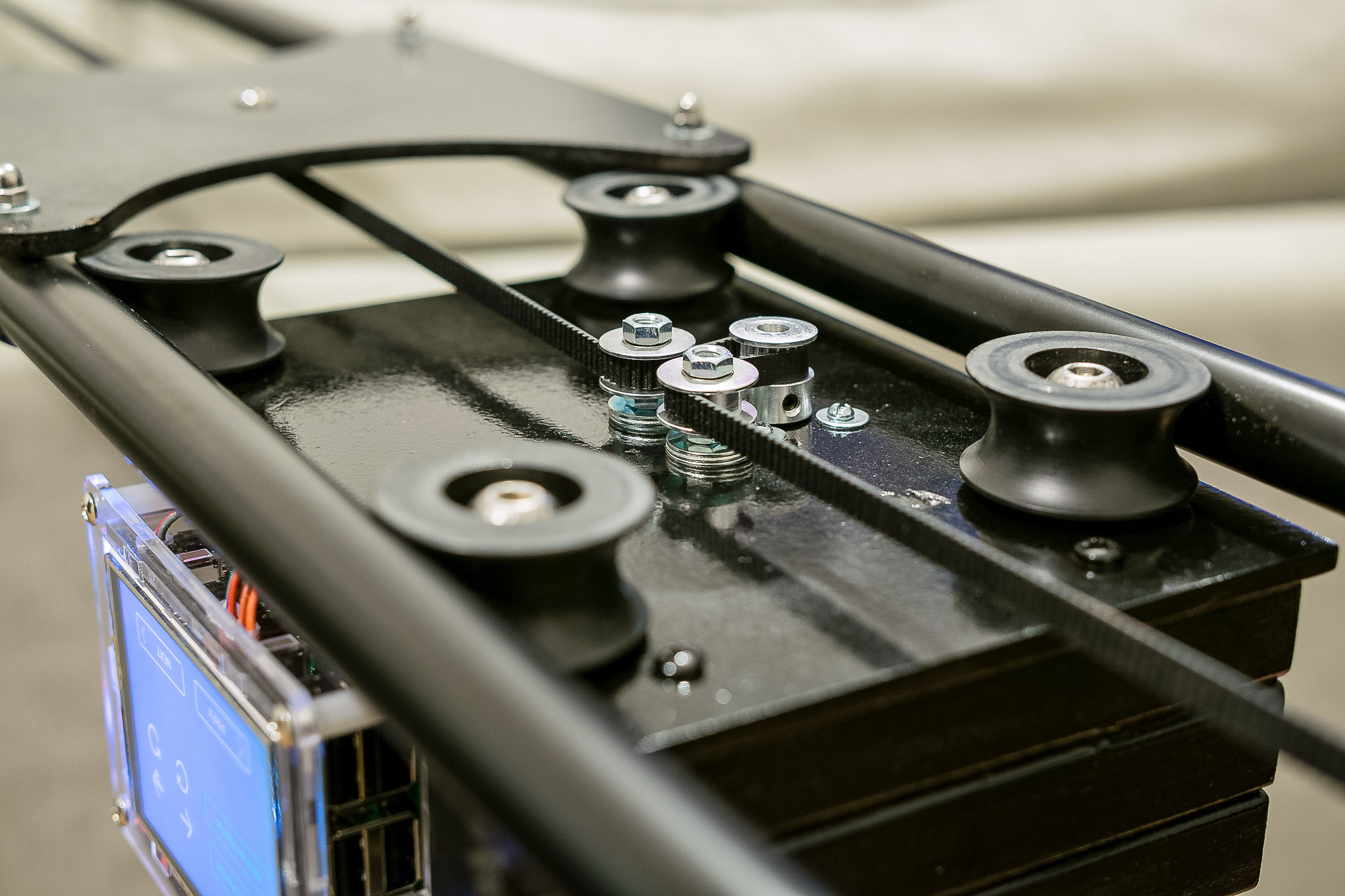
Most of the mechanical parts of the slider are based off a DIY camera slider from DIY Perks who made a great tutorial on YouTube. I modified his design to make a motorised slider with a timing belt.
Instead of copper pipes, I chose to use curtains rods from IKEA as they are cheaper, have greater tensile strength, and are already painted black. I might switch to carbon fibre tubes in the future if I decide I want the slider to be even stiffer than it is now.
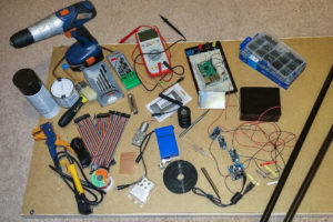
It started off like this:
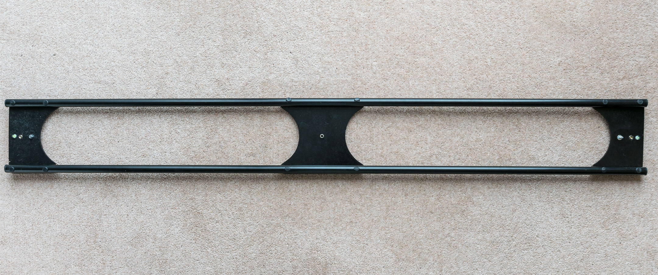
I took my time during the winter months to slowly build it up. The first version did not have panning capabilities and used MDF for the platform. It turned out not to be stiff enough as the weight of the camera combined with the sliding motion would make the whole thing wobble way too much for me to correct in post. It is probably OK for a small camera or a GoPro but not for a DSLR and a big heavy lens. As I was already thinking about version 2.0, I added that to the list of things to improve. Here is a few pictures of what V1.0 looked like
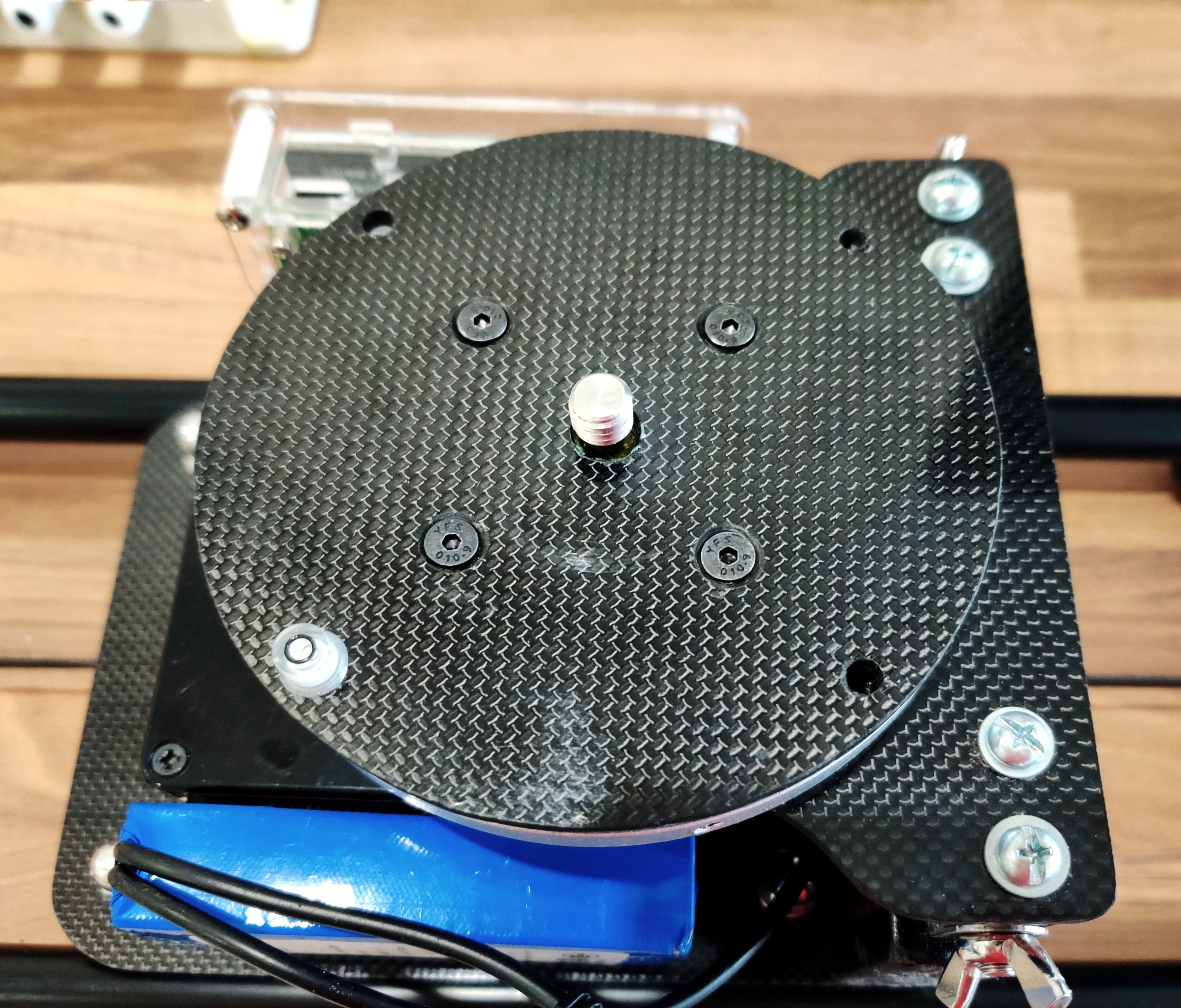
For V2.0, I added the panning capability and addressed the wobbling issue. As mentioned earlier, I used another motor to rotate a platform that would sit on top of a 120mm Lazy Susan bearing. This bearing gives good support to the platform while enabling smooth rotation.
To address the wobbling, I redesigned the whole platform using carbon fibre plates instead of MDF. It was a lot harder to cut, drill and file but it was worth it. The whole thing is as stiff as it can be, it is much more durable and looks better than the MDF version.


While doing the mechanical side, I also experimented with the electronics to decide which solution was the best.
Electronics
I chose to use a 12V rechargeable battery pack with enough capacity to run a time-lapse for a few hours. You can find them for a few quid on Amazon or eBay.
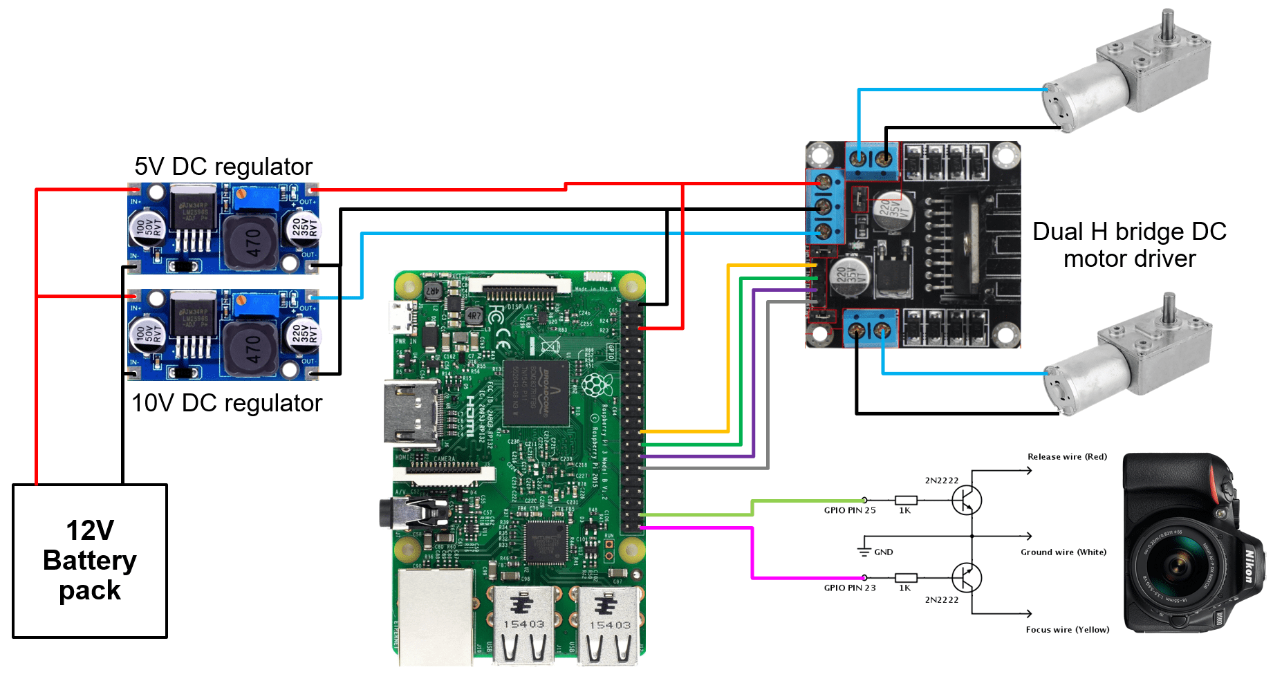
As the output of the battery is not stable enough as the battery discharges, I connected 2 LM2596 DC-DC Buck Converters, one for a 5V supply to power the Raspberry Pi and the display, one 10V supply to power the H-bridge and the motors. These are adjustable, small, very cheap and reliable enough to power the Raspberry Pi without risking frying it. On that note, I chose to power the Pi via GPIO pins 2 and 6 instead of using the recommended micro-USB port as I didn’t want to have anything plugged into the ports (other than the GPIO interface). Doing this is a bit more risky as it bypasses the supply fuse found on the micro-USB line so there is no short-circuit protection, but I was OK with it as the LM2596 has a built-in output current limiter that should hopefully kick in if needs be.
For the motor driver, I went for a L298N Dual H-Bridge motor driver as it can easily drive 2 DC motors using the GPIO pins of the Raspberry Pi.
For the motors, I hesitated a long time between stepper motors and DC motors. Stepper motors have better accuracy and torque but I wasn’t sure the minimum angle (step) would be precise enough for the movements I was going for without requiring external bulky reductors, so I went with DC motors of 10 RPM for the slider motor and 0.6 RPM for the rotating motor. I could tweak the power supply or use PWM to adjust the speed of each one as needed.
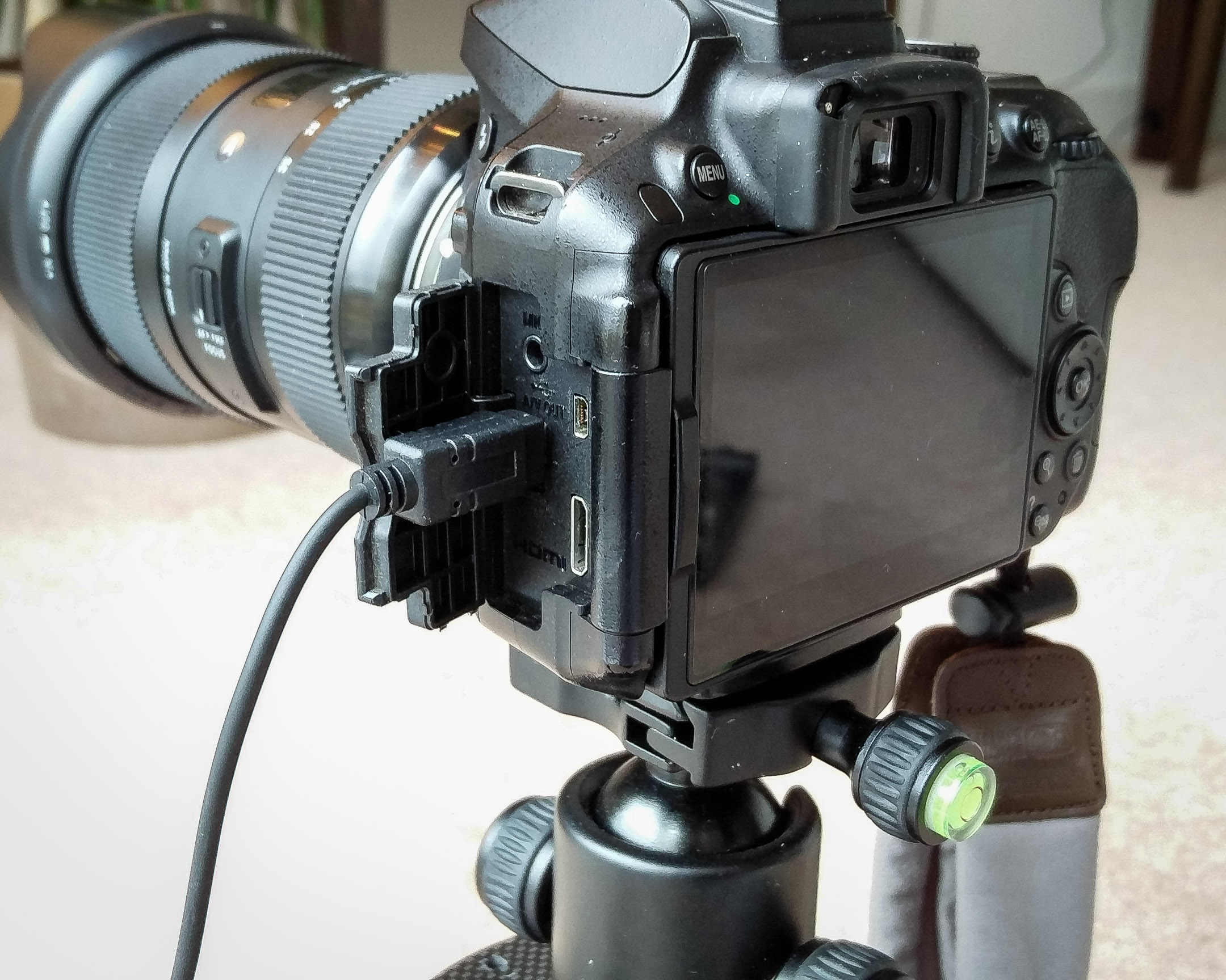
For the shutter release circuit for my Nikon camera, it is simple enough to build one. I had a few resistors and 2N2222A transistors lying around so it was just a matter of connecting things up to the focus and release wires of my camera using a prototyping board.
Here is a quick&dirty diagram of the electronics.
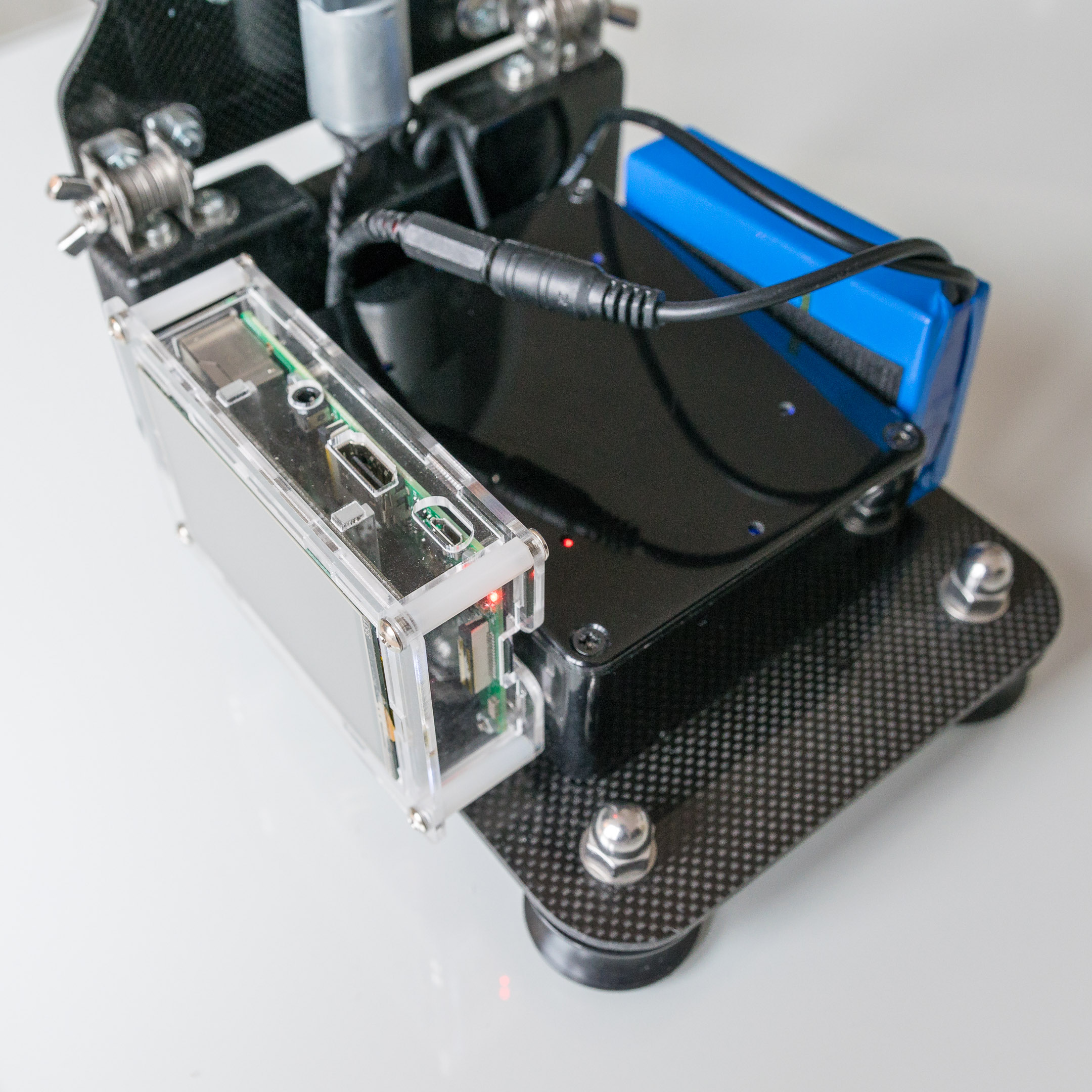
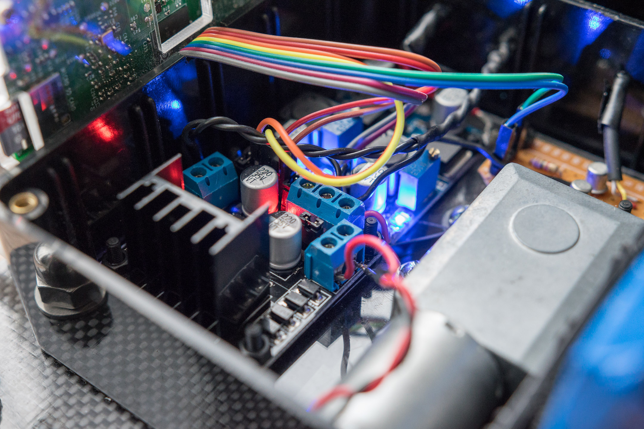
And here is a view of the ABS box that holds all the electronics and the sliding motor.

User Interface
This is arguably the most important part of any system from a user point of view. You can have the best system in the world with the best features, but if it has a rubbish user interface, it is seriously crippled. To me the best way to check and control the system was to use a touchscreen.
I looked online for touchscreens that would be compatible with the GPIO interface of the Pi and would still leave some GPIO pins accessible for me to connect the rest of pins to the motors and shutter release circuit. I found a cheap one on Amazon with a 3.5 inches LCD touchscreen and a 480×320 resolution. It’s far from HD quality but good enough for my simple UI.
I spent quite some time designing the user interface. I wanted it to be practical in the field and nice to look at. It doesn’t hurt does it ? 😉
As I have never designed a UI before, it was quite a trial and error process but I got there eventually. I used Affinity Designer to make it and here is a screen shot of the process.

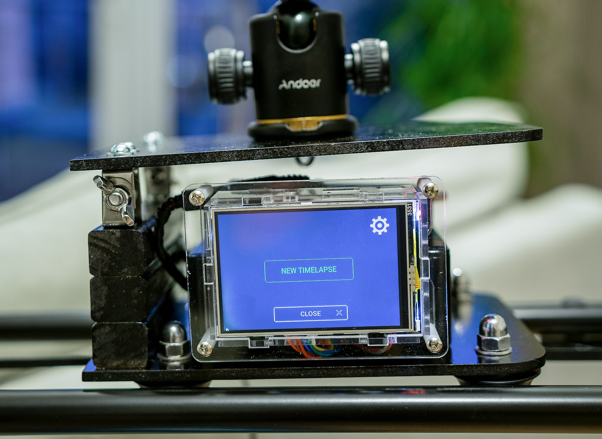
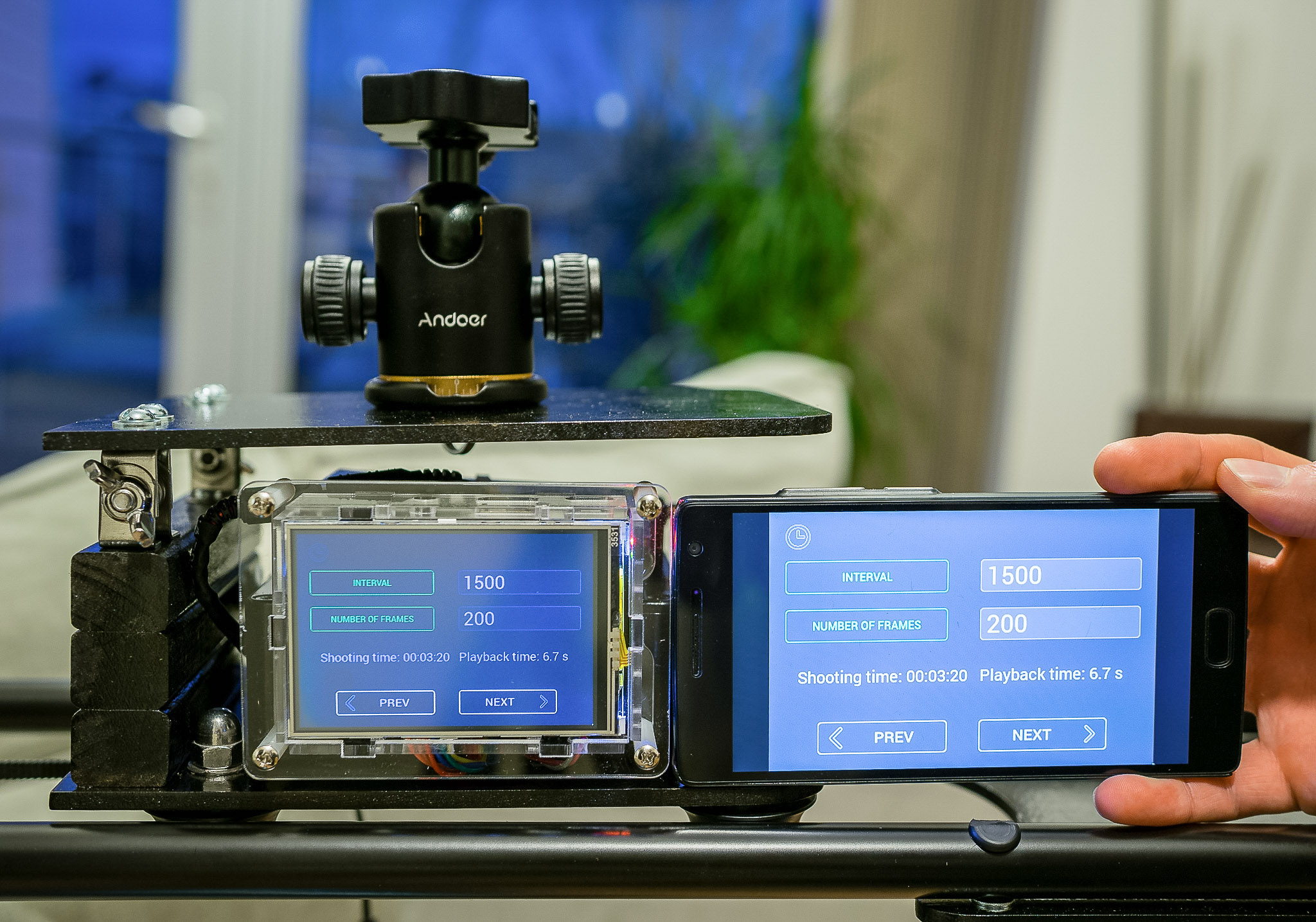
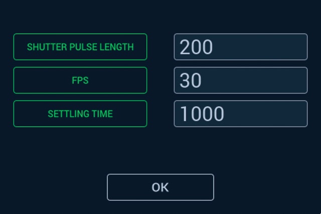
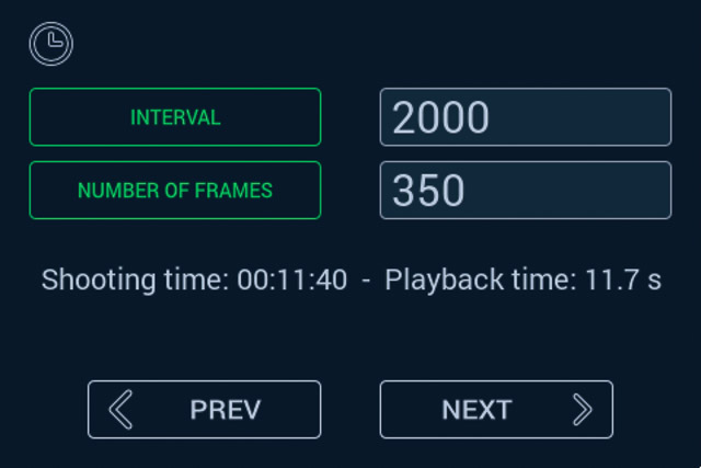
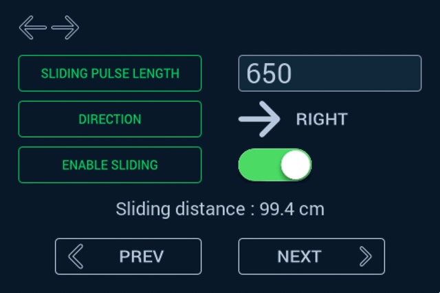
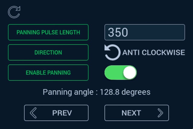
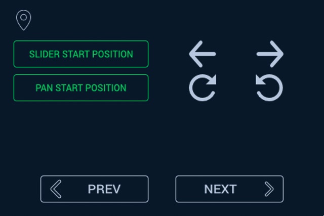
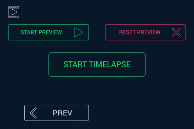
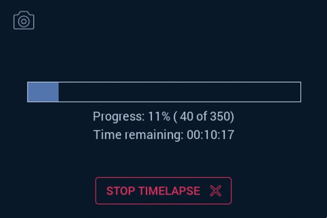
Here are some screenshots of the different screens I have created to control every aspect of the time-lapse:

Programming
Now that the system had a skeleton, muscles, eyes and a pretty face (OK, OK, I got carried away here), it needed a brain to make it all work. That’s were the programming comes in.
The program is written in Python using the Pygame UI library and WiringPi to control the GPIO pins. I used the code of a similar project called LapsePiTouch by David Hunt as a starting point. I modified the code to adapt it to my new UI, I added new configuration parameters to finely control every aspect of my system, added some feedback to the user to see how the system is behaving and I added multi-threading capabilities to be able to run multiple things in parallel. The main program controls the UI and spawns the main thread that runs the time-lapse. This thread spawns one thread for the sliding motion, one for the rotation, and one to drive the display back-lighting (it turns out my display does not support turning the back-lighting off but the thread is coded in case I switch to a better display in the future). All these threads communicate via global variables (I know, it’s not a great coding practise) and built-in inter-process communication for synchronisation points.
Making it even better
At that point the slider was working and I was very happy with it. A few days later, I realised that my Raspberry Pi 3 had WiFi capabilities and a bright light bulb went up in my head. How cool would it be to use the WiFi to connect to my system and control it remotely using my smartphone?
I was really excited about this. This was the feature that would make that thing on par with professional equipment. And the best part is, it wouldn’t cost me a penny other than figuring out how to make it work and spending time configuring everything.
The easiest way to do it was to use VNC to connect to the Pi. By default, the Pi connects to my home WiFi network so it is just a matter of running a VNC server on the Pi and connect to it via my home WLAN. It’s all well and good but it doesn’t work on the field where I have no WiFi network to connect to.
The solution was to write a small script that would run when the Pi boots and scans all the available networks. If my home network is in reach, it would connect to it and if not, it would create its own access point so that I could connect my smartphone directly to the Raspberry Pi WiFi hotspot. Once done, I always had a way to connect to the Pi and remotely control my system. Very cool and practical!
I could have written a dedicated app instead of “just” using a remote VNC connection but the time I would have spent on this was not worth it in my opinion.
As everything else, it did not work at first but I persevered and managed to make it work. Now I have time-lapse slider I can remotely control with my phone or tablet, check the status when capturing a time-lapse, and abort it if needed.
It turns out that this feature is absolutely necessary for something I did not anticipate before trying it in the field. You see, I used a cheap touch-screen that has very limited contrast and luminosity. It is OK in most cases, but when using it on a very bright day, the screen appears completely black and I cannot see a thing on the screen. Because smartphone screens are of way better quality I can still see something on it in the same conditions. So when it’s too bright outside, which admittedly doesn’t happen very often in the UK, I use my smartphone to control the slider.
Video Slider update (June 26th, 2020)
I have been thinking about how the slider could be used for shooting video instead of time-lapse for a little while. Because of the specific move-stop-shoot-move behaviour required to get perfectly sharp pictures suitable for a time-lapse, the slider is not very suited for video use. The hardware is all there but the controls are not and you would end up with very jerky footage.
A recent comment from SCOTT was all I needed to motivate myself to update the code to enable that use case. I have spent a few hours updating and testing the code, updating the UI to reflect the new video mode and I am happy to report that I have got something that works and the slider can now be used to shoot video.
What I did is create a separate video thread that smoothly controls the motors and that’s it. Well, technically it was not that simple 😉 . To still be able to control the speed of each motor, I switched the sliding motor control to PWM control. The panning motor was already using PWM so there were no modifications needed there. Unfortunately, all the hardware-PWM GPIO pins are already in use 😐 . As I didn’t want to rewire the GPIO pins to support hardware-PWM on the sliding motor, I decided to use software-PWM. While a bit less accurate than hardware-PWM, it can be implemented on any digital GPIO pin. The accuracy is not really an issue for the motor control and after some testing, it seemed to work great so I went ahead and modified the main Python code.
As I didn’t want to modify the main time-lapse feature, I decided to change the UI to show it as a completely different mode on the start screen (even though the code underneath reuses most of the existing features).
When selecting “New Video” on the start screen, you are now presented with the same sliding and panning controls as the time-lapse feature with a slight difference: while the motor controls in time-lapse mode are a pulse in millisecond, it doesn’t make sense for a video so I changed that to a “motor speed” which is now a percentage (from 0% to 100%). Setting the speed to 50 will make the motor move at 50% of the maximum speed. I’ve put some safe-guards in the code to cap the input value at 100 in case the user enters a greater value by mistake.
I have removed the first screen where you would set the number of frames and the interval between each frame because it doesn’t make any sense for a video. I have also removed all shutter controls in video mode because the external shutter release on my camera only works in photo mode. So you would need to press record before starting the slider and stop it manually at the end but that shouldn’t be an issue. Every other control and feature stays the same.
I have updated the downloadable archive with the latest code and icons. I hope you enjoy this new feature and make good use of it. 🙂
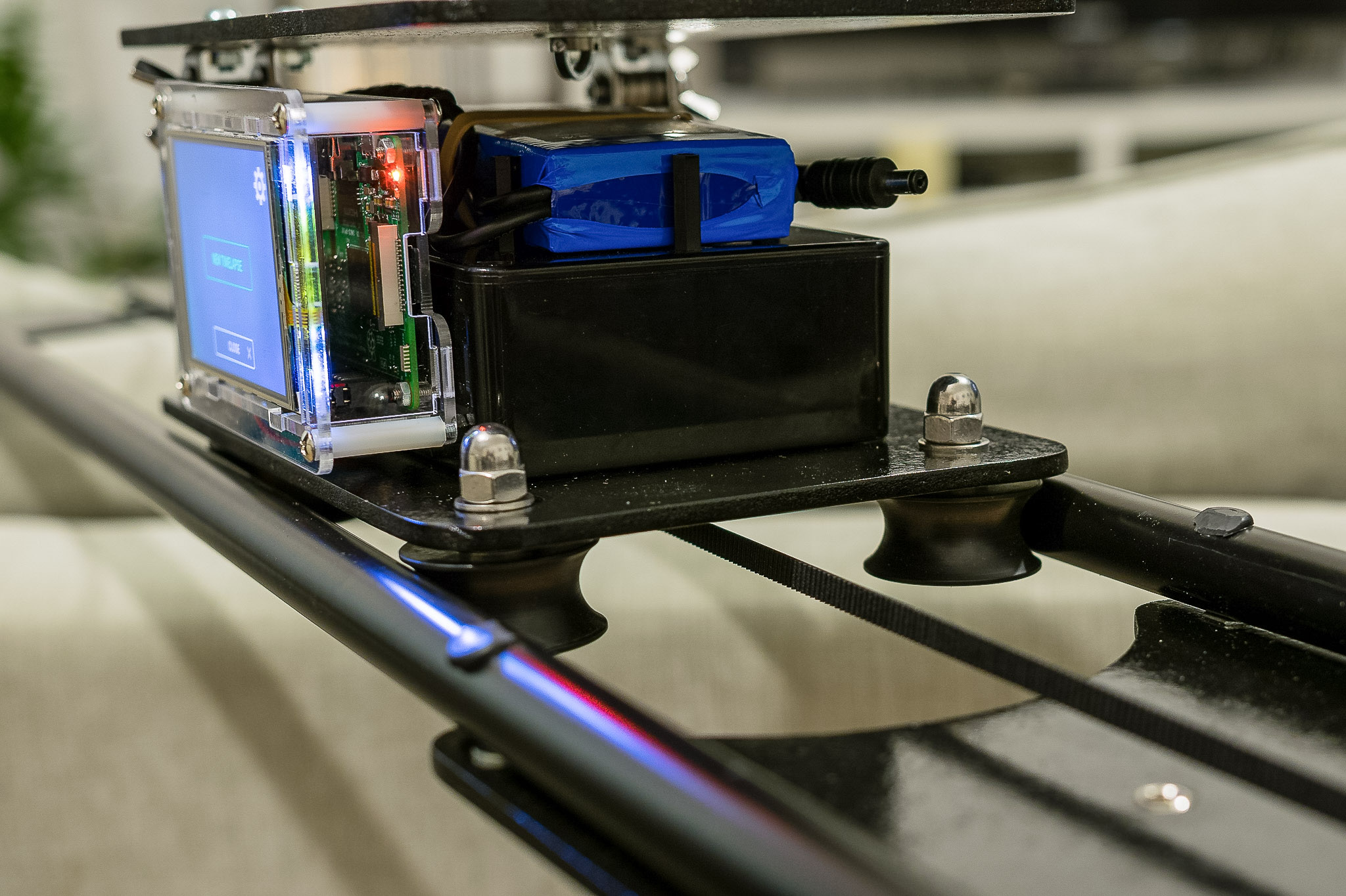
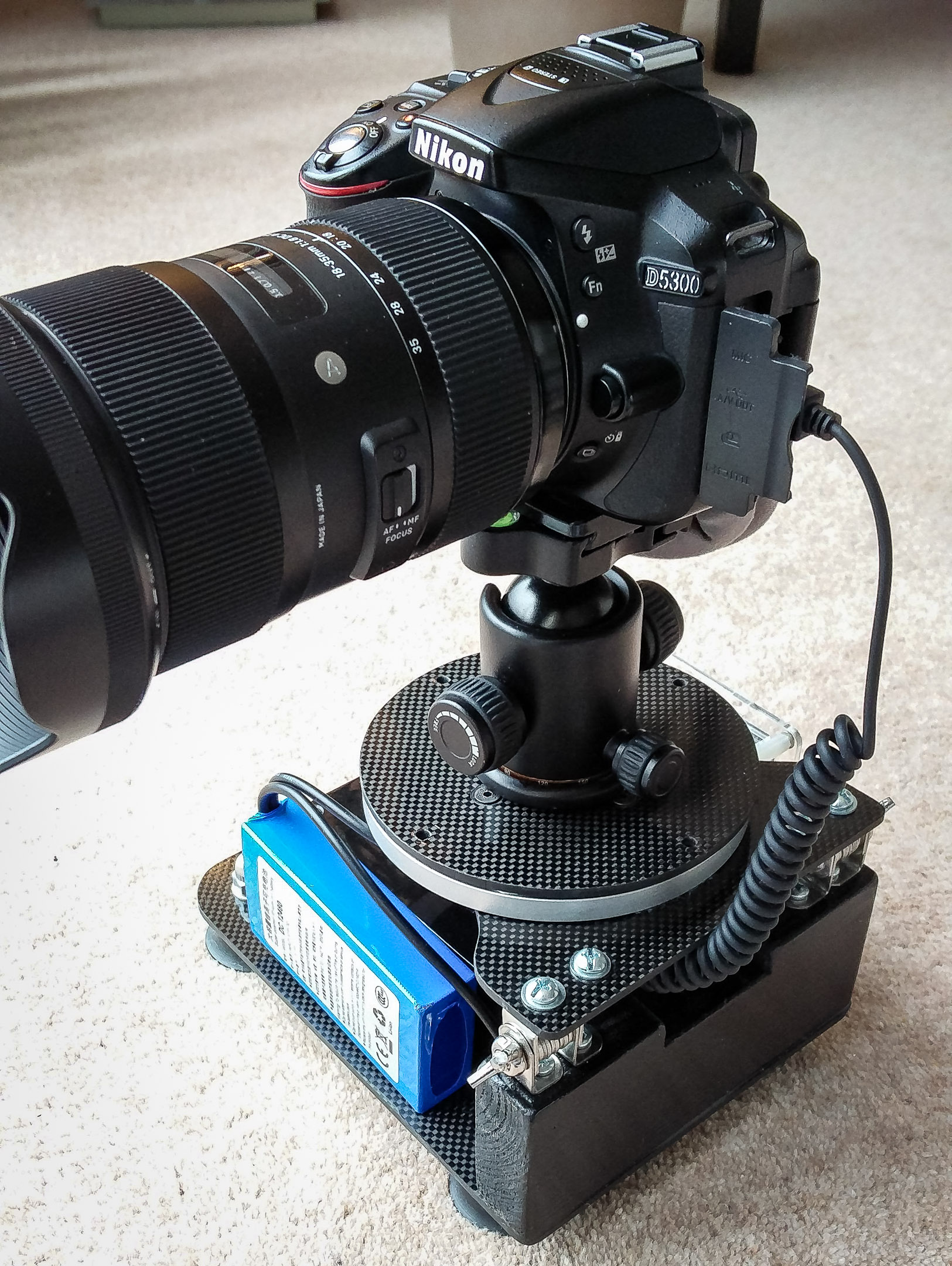
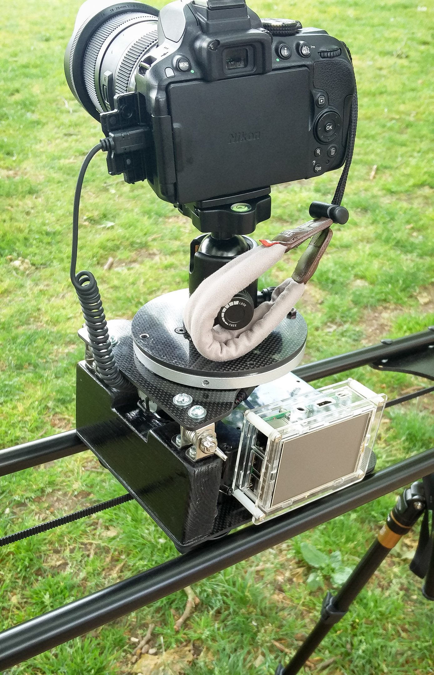
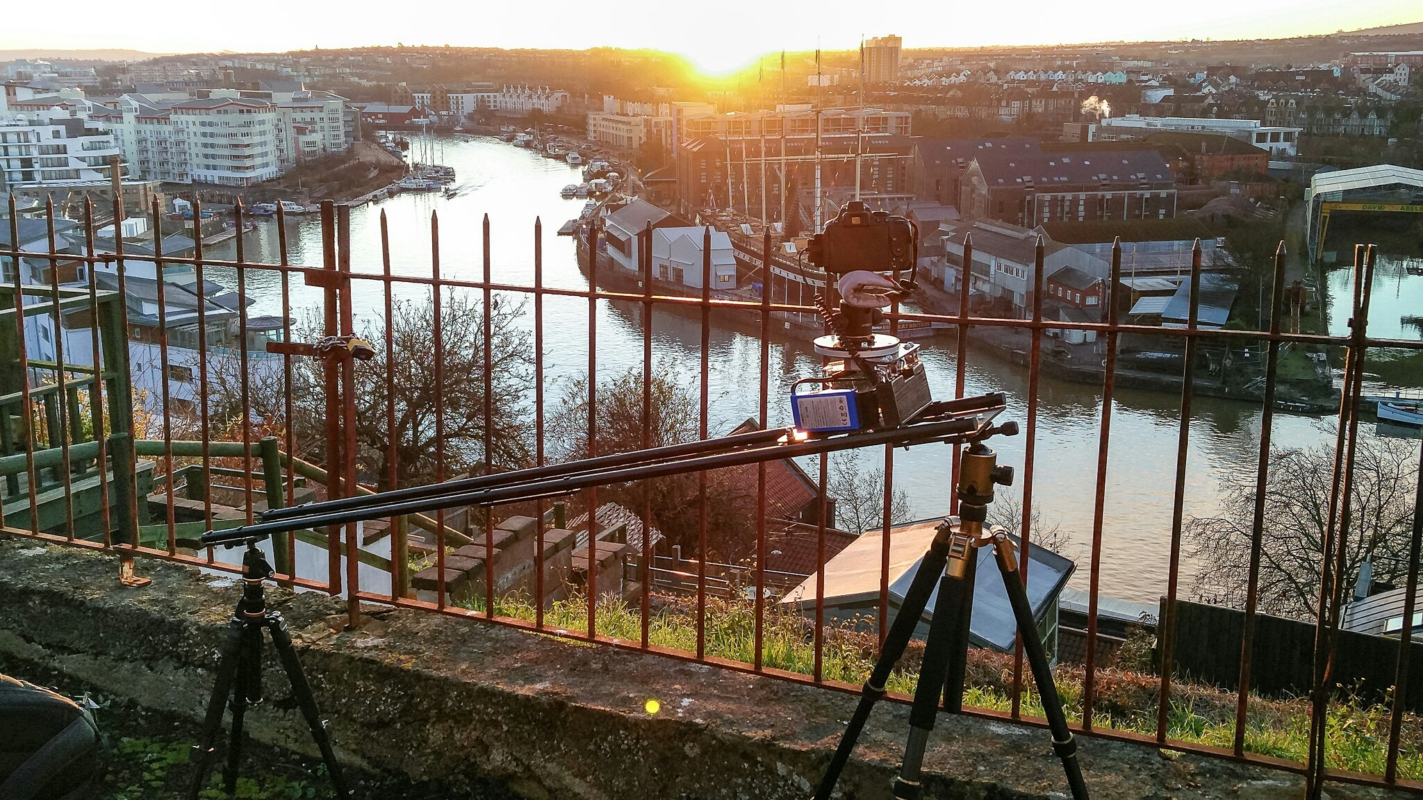
The finished slider
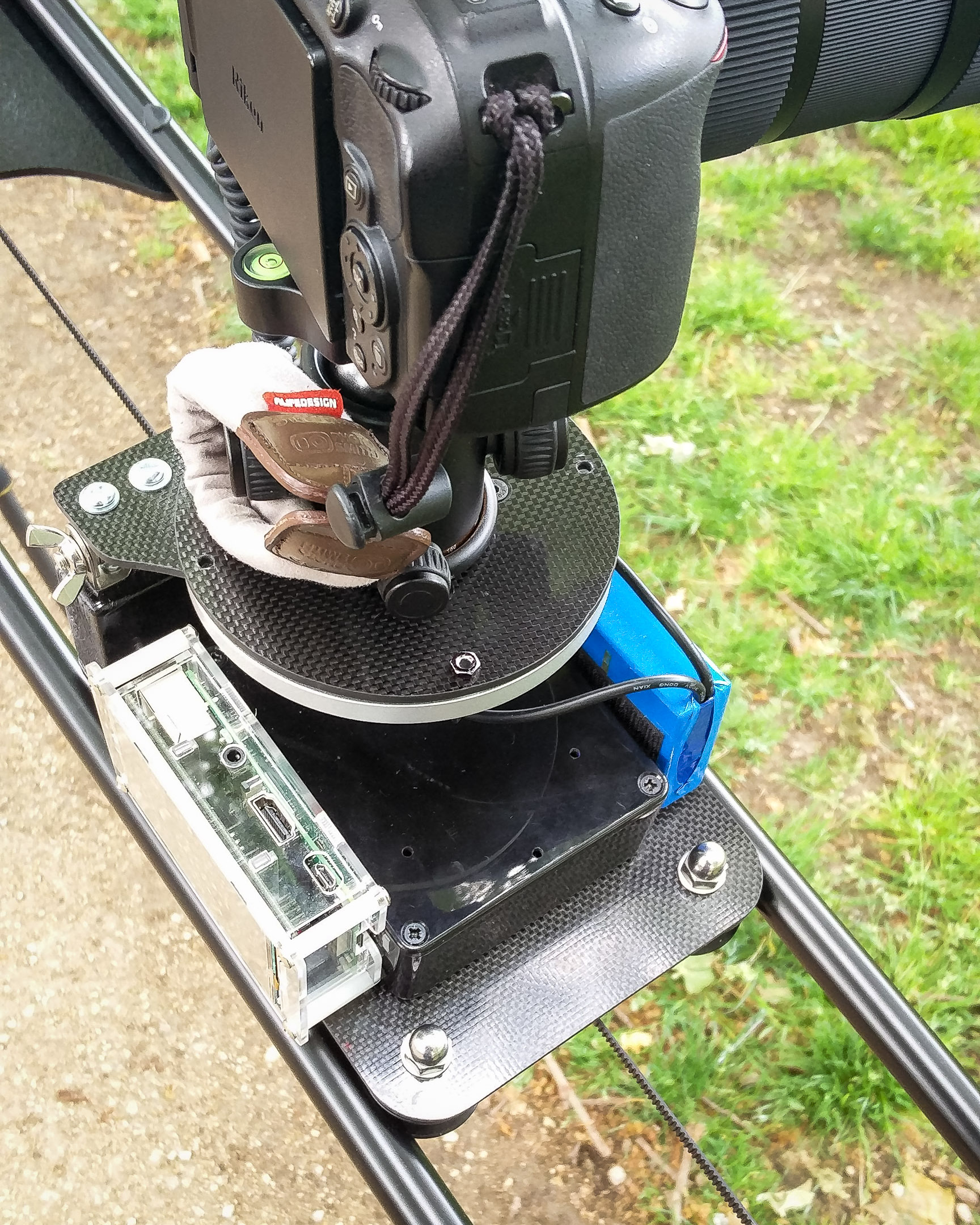
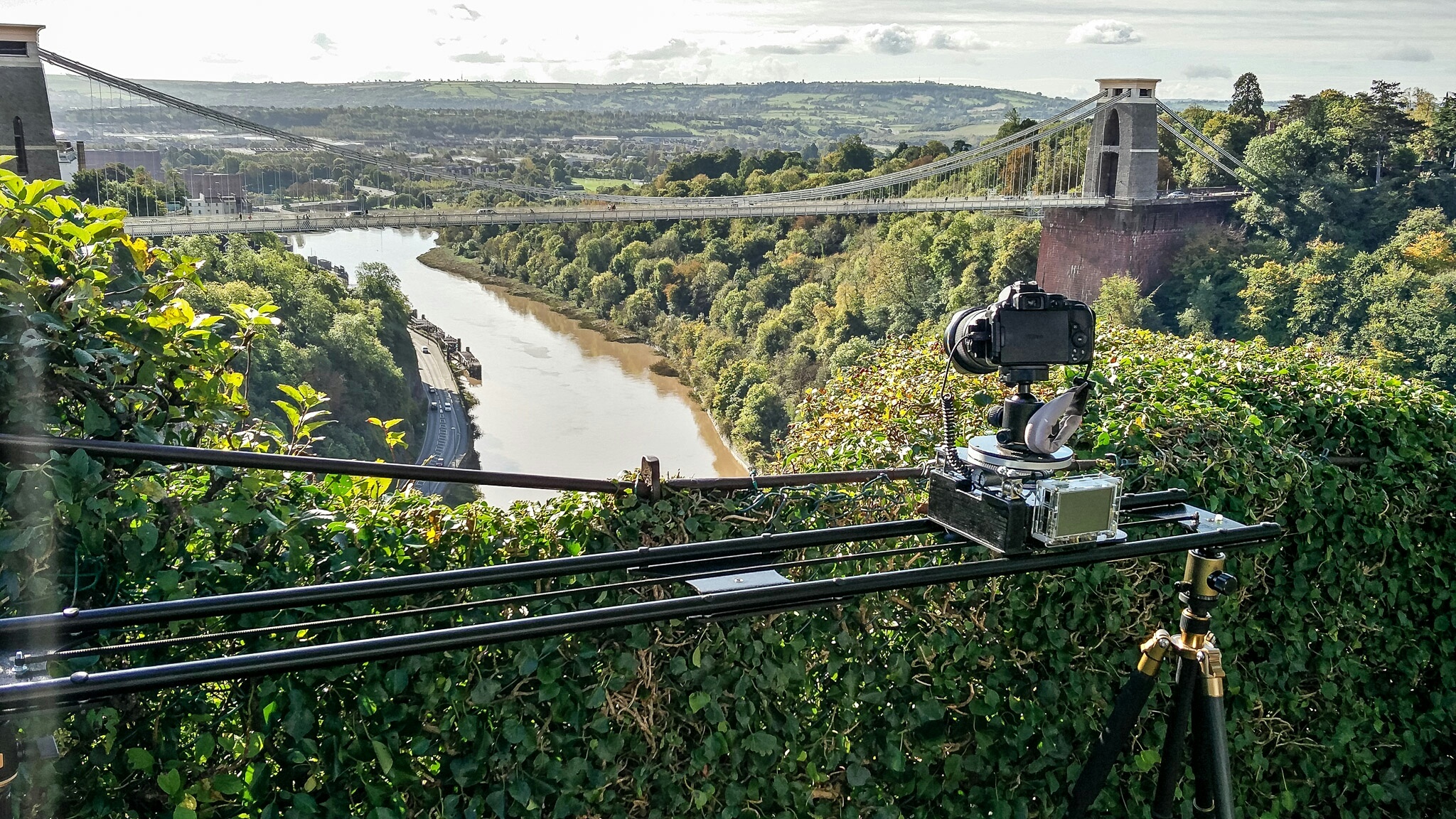
Here are some pictures of the finished project in its environment:
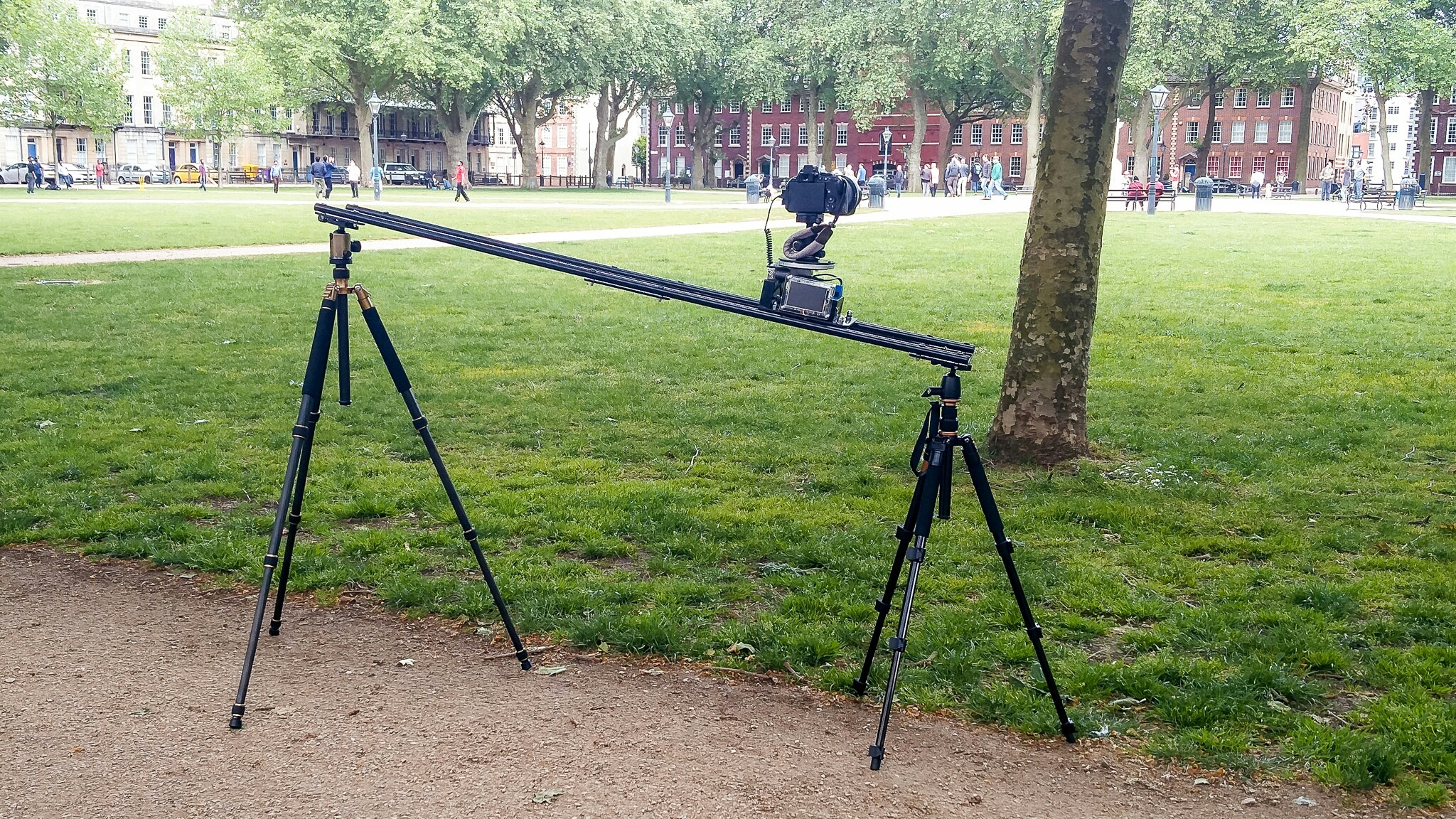
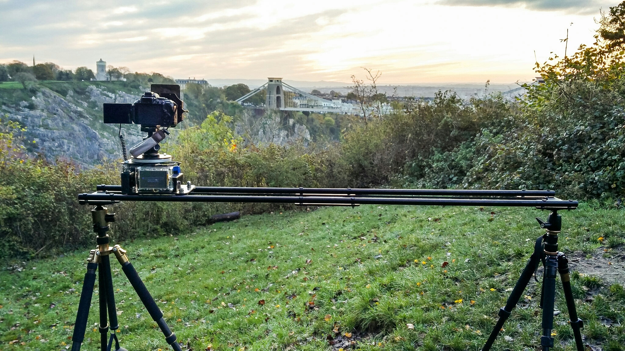
It was a lot of fun to do and it kept me busy during the winter months. The whole thing cost me around £150, which is way cheaper than anything similar on the market.
With it, I was able to capture much more interesting time-lapses, some of them can be seen in this time-lapse of Bristol.
Download link
If you want to re-use my code for your own slider, I created an archive with all the code and resources to run the controller. I have also added templates of all the Raspbian configuration files that I modified to make the whole thing work and a list of the external packages I needed to install. You can download it here:
Room for improvements
I have been using this system for more than a year now, and there are a few things I could improve to make it even better,
Build precision
I built the whole thing in my flat with a very limited set of tools. On top of that, materials like carbon fibre are notoriously hard to cut or drill. Even with all the accuracy I could muster, some of the build could be more precise and accurate. A real workbench and a vice would have help me a lot but I didn’t have those. Ideally, cutting all the parts using a CNC machine would be perfect but the cost of those was too much for me. In the end, the slider is very strong and stable (as Theresa would say 😉 ) but there is a bit of wiggle room in the rotating platform. It would have been nice to get rid of it but it’s not a big issue and I can deal with it in post-processing.
Motion accuracy
I used DC motors for all the moving parts. They are more flexible to work with and smaller but they are less accurate than stepper motor. If I had to do it again, I would probably use stepper motor for the sliding motor. I couldn’t use a stepper motor for the rotating platform without some sort of reductor to be able to get a very precise angle. The problem with this solution is that a stepper motor attached to a reductor would be too big to fit on under the platform without some clever mechanical design that I cannot achieve myself.
Safety
This is something I didn’t think of when building the slider but it wasn’t long until I realised a flaw in my design when using it for the first time. There is no limit switch on the slider. It means that If I don’t set up the time-lapse correctly, there is a possibility that the platform can hit the end of the slider and damage it. I am planning to add 2 limit switches so that the slider stops itself (or goes back in the opposite direction) when it reaches one end of the slider. The source code is ready for this. I just need to find a good way to add those switches to the platform.
Updated 25/07/2018: As I will soon need to shoot a time-lapse while leaving the slider unattended, I decided it was time to add limit switches to the existing slider to avoid damaging it. Here is how I did it:
I cut two thin pieces of wood of approximately 8cm long and 1.5cm tall that would fit between the rails without touching the platform. One end of each piece has a bevelled edge. This is very important so that when the limit switch is hit, the slider can still travel for a few cm without hitting the end of the rail. That way, I was able to implement an easy in/out movement. The resulting time-lapse would be much more aesthetically pleasing than if the slider stopped abruptly when hitting the switch.
I painted those pieces of wood black and glued them at each end of the rail and glued 2 limit switches underneath the sliding platform. I made sure the system was symmetric at each end. I drilled a hole through the carbon fiber platform and the ABS Box holding the electronics to pass the wires into the box so that all electrical connections are protected from the outside world. That’s the mechanical side done. After that, I connected the output of each switch to a GPIO pin of the Raspeberry Pi (while I connected the common contact of the switches to the ground of the system). I configured those 2 GPIO pins to use the internal pull-up resistors. This way, I can connect them straight to the Pi without requiring external resistors. Neat!


After this I modified the code so that the slider stops after hitting the switches. When coding it, I decided to add new configuration parameters to control the behaviour of the system when one of the switch is hit. I added the possibility to either directly stop the slider or have a configurable ease in/out movement. In my opinion, an ease in/out option leads to much better time-lapses. I also added the ability for the slider to go back in the opposite direction once reaching the end of the slider. This way, I can leave it loop indefinitely without risking it being destroyed. I also added a couple of error and diagnostics message so that the user knows what’s happening at any time. I have updated the downloadable archive with the new code and updated UI/icons.
Display
As I said earlier, I used a cheap display for my slider. It is fine in most situations but it is impossible to see a thing in bright conditions. I might upgrade the touchscreen in the future for one that has better contrast. It would also be nice to be able to control the screen back-lighting. This way, I could switch off the screen while the time-lapse is running to save power and limit the reflection in my camera.
Software
There are many improvements that can be added to the code. I might add a few more configuration options in the future. Here are a few things I thought about:
- Being able to set keyframes with different speeds between them
- Add the ability to have ease-in or ease-out movements
- Use Bezier curves for more creative control of the speed of each motor
- Connect the camera via USB and display EXIF data and histogram on the fly while the time-lapse is running
Some improvements are easier than others but the good thing about software improvements is that it doesn’t cost a thing. I just need time to code them.
Removable platform
Right now, the slider is not modular. I cannot remove the rotating platform even if I don’t plan to use it. The same thing is true for the sliding motion. For example, I might want to shoot a time-lapse with rotation motion only. As of today, I cannot remove the platform from the slider and fix it to my tripod. That means I have to bring the whole slider with me even if I don’t need the slider. I might modify the platform in the future to be able to do this.


26 thoughts on “Making a DIY time-lapse and video slider”
Seriously impressed man. This is awesome. Particularly liked your shot in bristol of the air balloons. Inspired!
Thanks Scott! The balloon sequence seems to be everyone’s favourite 😉
you are actually a good webmaster. The website loading velocity is amazing. It seems that you are doing any distinctive trick. In addition, The contents are masterpiece. you’ve done a excellent process on this subject!
How much didn’t you spend on everything? I think I will do a similar one based on your design. It looks amazing. I might improve some of the features as you mentioned.
Thanks a lot.
Hi Rodrigo!
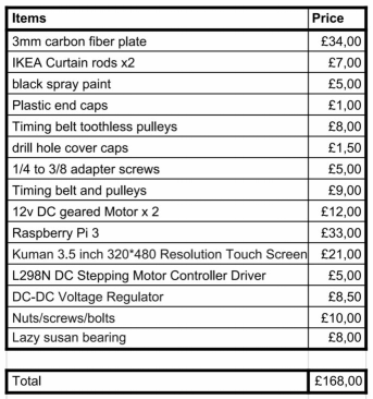
Glad you liked that project! The total cost at the time of the build was 168GBP (see details in the spreadsheet below).
I would be curious to see your build once it’s done. Let me know when you have something to share.
Cheers
Hi, thanks for you reply. I was wondering about the display you used. You said you bought a touch screen display compatible with the GPIO interface, I am not sure if all displays sold on Amazon for the Raspberry are compatible with the GPIO interface, it does not say. Here is one example I found https://www.amazon.ca/gp/product/B07YDBFY8F/ref=ox_sc_act_title_5?smid=A34CQKEVNF2MJX&psc=1
Will that work?
Thanks again, you can write me to my email.
Hi Rodrigo,
Yes, it looks like that display is perfect for that. However, it does differ from mine in the sense that the video input is from the HDMI output of the RPi and from what I can see in the description, the GPIO is only used for power and touch inputs, but I don’t see why this would be an issue. It might actually be better than my solution since it would free up some GPIO pins for greater expansion in the future if you decide to add more stuff to your system. The possibility to control the back-light is also great IMO (something that my system lacks).
Hi Go-pixL, you have done an amazing job on this project and I want to thank you for sharing it with us. I do have a question about the code. I would like to take this from a timelapse to full motion video camera on my slider. Therefore, I don’t need the settling time to capture images. I want to put a video camera on my slider and have it slide back and forth smoothly. So I have studied the code for hours, and can’t figure out how to disable the settle time and change to just smooth movement. Do you have any recommendations?
Thanks Again.
Hi Scott!
I’m glad you like the build. The use case you describe is actually something I’ve been thinking about myself.
I had a look at the code to see what would need to be modified to allow for such use case. Because of the way the sliding and panning thread are spawned, there are several things that would need to be modified to make it work. At the moment the slider moves for a bit, then stops, takes a picture, and starts again.
To allow for video use, you would need an infinite loop and instead of a timed-pulse at max speed, you would need to switch the motor controls to PWM to allow you to smoothly control the speed of each motor independently.
I don’t know if that makes sense?
The good news is that the existing hardware should support all this. Only the software needs to change. 🙂
I’ll see what I can do and if I have something that works I will update this post and the attached code, so keep an eye on this post in the coming days.
Cheers.
Hi Scott,
I am happy to report that after a bit of coding and testing last night, I have something that I think works great for video now. I have updated the code and icons in the archive.
For more details on the update, have a look at the update section.
Thanks for giving my the push to update the code and happy shooting. 🙂
Hi there, trying to create something similar to help my daughter with her cinema studies college work. I understand how you created the lazy susan platfom, can you share how you attached the tripod head flush to the top of the platform and the motor (presumably co-axially) to the bottom on such a thin plate?.
Hi Stuart,
Thanks for the comment. The way I tackled with isn’t my proudest work i must say, but it does the job. Since I wanted to be able to access the inside of the rotating base for maintenance purposes and potential future improvements, I had to do it in a way I could disassemble it.
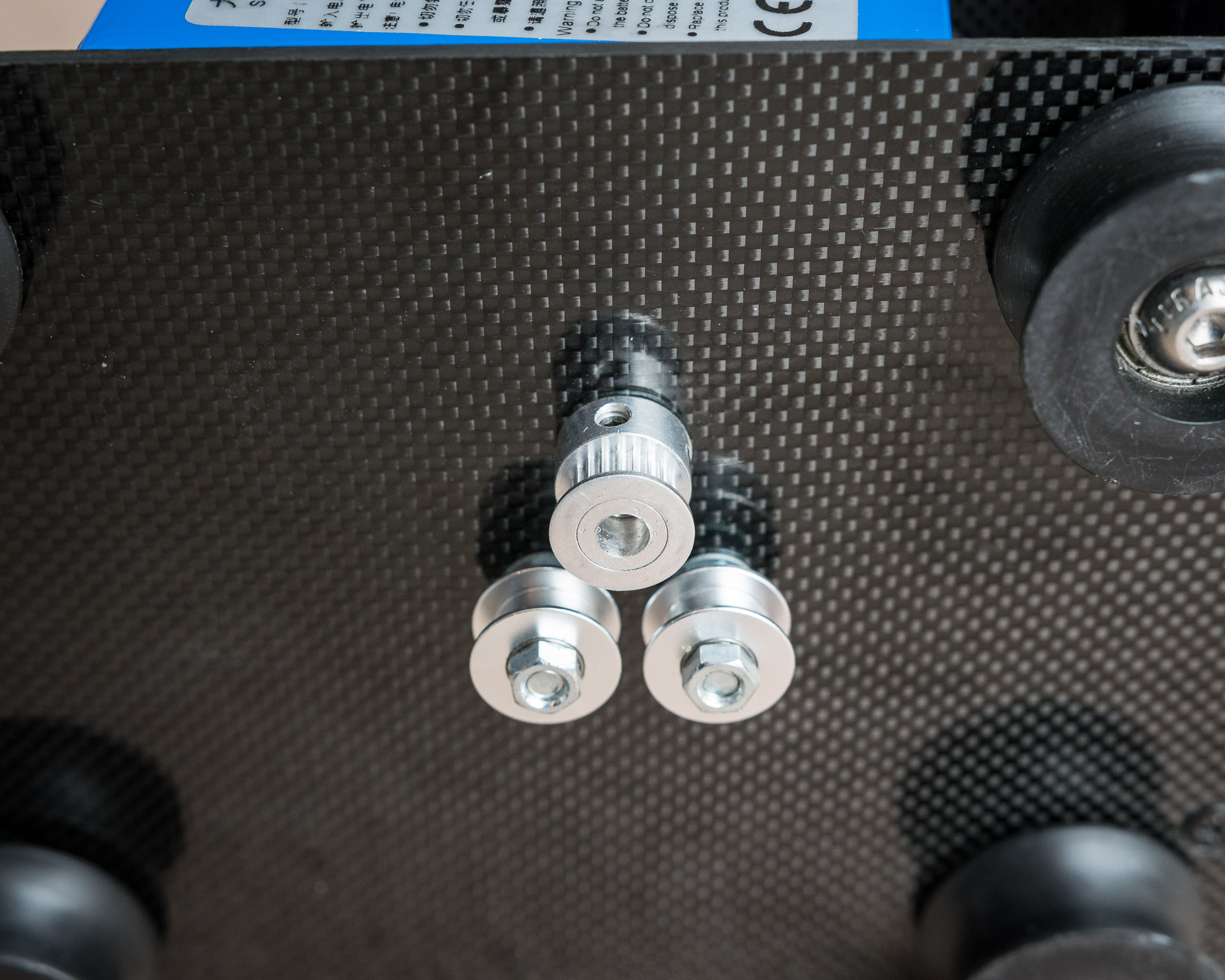
What I ended up doing was cutting a circular adaptor plate out of carbon fibre which is glued directly onto the motor shaft using epoxy resin (not the prettiest job) and fits inside the Lazy Susan bearing.
On this plate, I also glued some nuts and washers that I can thread hex screws into from the top plate. I had to make sure the holes on both those plates are perfectly aligned. I also countersunk the holes on the top plate so that the screw heads are flush with the surface of the plate and don’t interfere with the ball head that screws into the main 3/8″ screw at the center of the top plate.
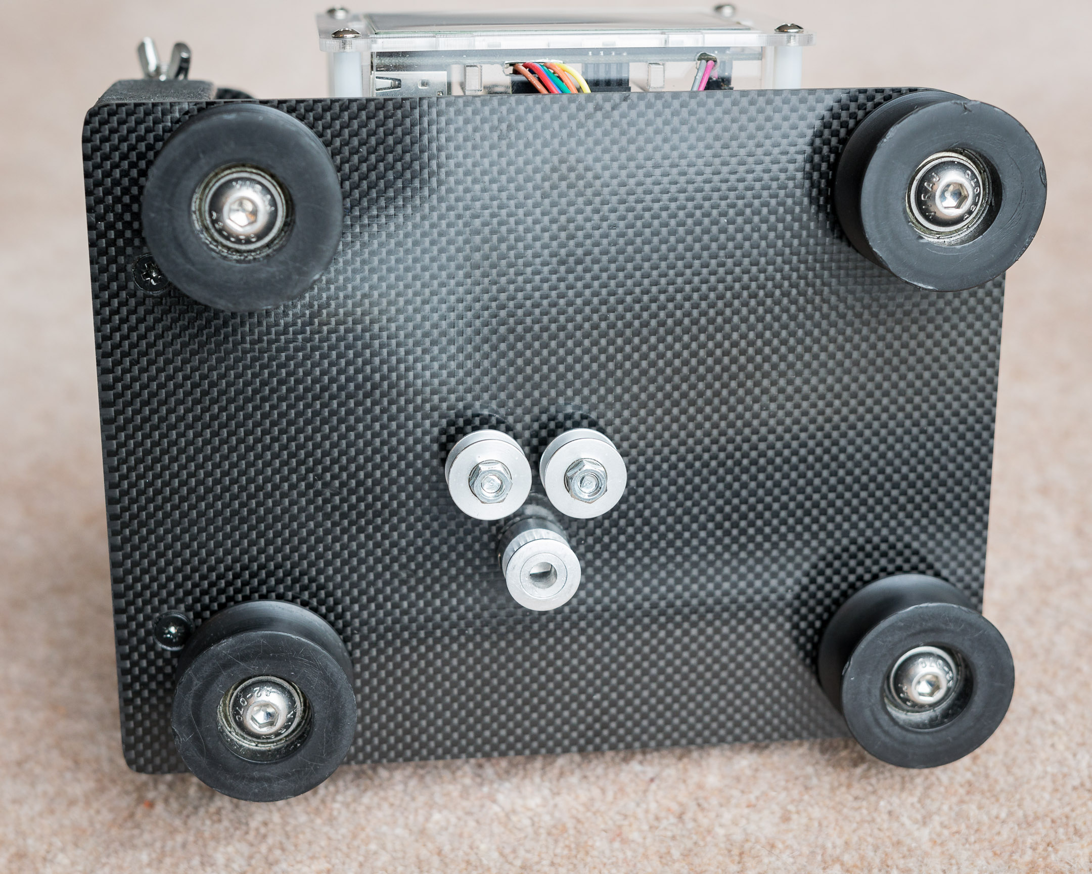
The motor itself is just screwed directly to the bottom plate as you can see in one of the picture in the gallery above, with the shaft poking through. The motor shaft was too long to fit within the thickness of the Lazy Susan bearing so I ended up cutting a few millimetres off.
Here is what the adaptor plate looks like:
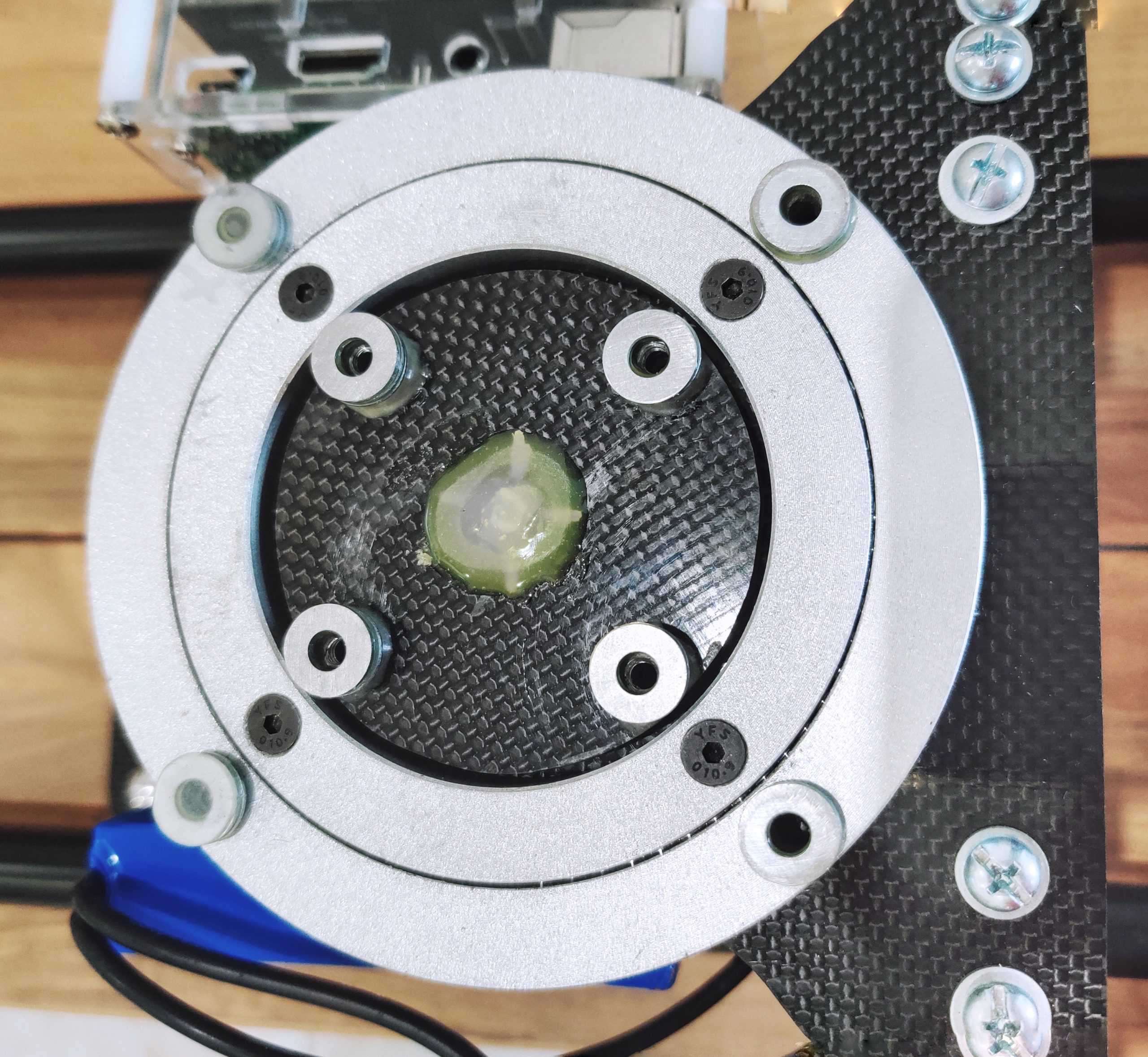
And here is a picture of the top plate with the ball head removed:
I hope it helps.
Let me know if you have any more questions.
Thanks for the quick answer.
I am using the IKEA curtain rods and getting the braces and the dolly 3d printed by a friend. The control part will be fun and I hope i get it all working in time for her project.
I have two stepper motors so will need to work out the control differently.
So just to be clear for me, the smaller carbon fibre disc is glued to the motor shaft and rotates free of the inner part of the bearing which is screwed to the hinged top. The main disc attaches the outer part of the bearing to the smaller disc (and the motor obviously). I think I understand that. Sorry i am not clear how the 3/8″ screw is fitted to the top plate?
I am thinking of printing something to do this, something not dissimilar to a labyrinth seal. I will make a model on the pc and post it on here for you to see if it makes sense? Ta
Yes, that’s exactly right. The 3/8″ screw is also glued to the back of the top plate with epoxy.
That sounds like a good plan. If I had to do it again, I would probably choose stepper motors as well. I think that’s the right way to go when accuracy is key. They are a bit harder to fit in tight spaces though…
Having those adaptor plates 3D printed is a great idea. It will definitely result in greater accuracy and much better finish. I wish I had access to one of those.
One thing to bear in mind if you are using 3D printed parts is the rigidity of the finished assembly. It is not a concern if you are only doing horizontal panning and the weight of the camera is resting roughly on the axis of rotation. If you are planning to use the hinge mechanism to do vertical tilts however, the weight of the camera becomes off-axis and the stiffness of the adaptor plates becomes crucial. I’m not familiar with how stiff PLA-printed parts are but I thought I would let you know.
Can I post pictures on here? Making progress but I can see why you made your dolly a lot bigger!
Hi Stuart.
Unfortunately you can’t post pictures directly in the comments. However you can send them at contact@go-pixl.com and I will upload them here if you want.
I couldn’t have made the dolly any smaller without access to custom parts or a 3D printer.
Emailed a screen grab of the my first prototype (still waiting for some parts to be printed before I can physically try anything.
Hi Again.
I have a working prototype now, motors installed and driven but I am trying to work out how to smooth out the stepper motor movement. I am using the adafruit hat for Pi and in the sample code there’s single steps, double steps, interleaved and microsteps, the microsteps are smoothest but on most sites I’ve seen you can vary the micrsteps as in 1/8th or 1/16th or 1/32nd but I haven’t worked that out yet. I need to find out more about the control code.
Take a look into this video it explained how to use a stepper motor with a raspberry: https://youtu.be/LUbhPKBL_IU
hi thank you for sharing this project with us. I’m just wondering if there is any progress in converting to stepper motors. Thank you again
What an awesome build. I have one using Arduino and now getting into Pi. I want to swap mine to a pi version with a touchscreen but also add my own touch. I tried downloading the project but the download link after the captcha is broken
Once again, awesome project
Hi John!
Thanks for letting me know about the download link. I don’t know what happened there but it should be fixed now.
Let us know how you get on with the project 🙂
Xavier,
I looked at this a few days ago, and was very impressed. I’m basic atm (the motorisation feels out of my league!) so I came here via the DIY Perks Youtube with the intention of asking you where you got the rollers because his link no longer works.
I didn’t fully understand the benefit/function of the slider for time lapse but I just watched your video of Bristol and I am blown away. Great work! Especially the panning shot of the bridge with the hot air balloons in the background?! Mega. Again, well done!
Thanks for documenting the whole thing. I am going to make the slider first of all, after that, I will think about motorising it 🙂
Thanks Conor. Really appreciated. 🙂
For the rollers, if you search for “0840UU guide pulleys” you should find what you’re looking for.
For example, this one https://www.ebay.co.uk/itm/142922577134
Brilliant, Xavier, thanks for getting back to me. They’re ordered now!
Can’t wait to build it!
Best wishes
Conor:)